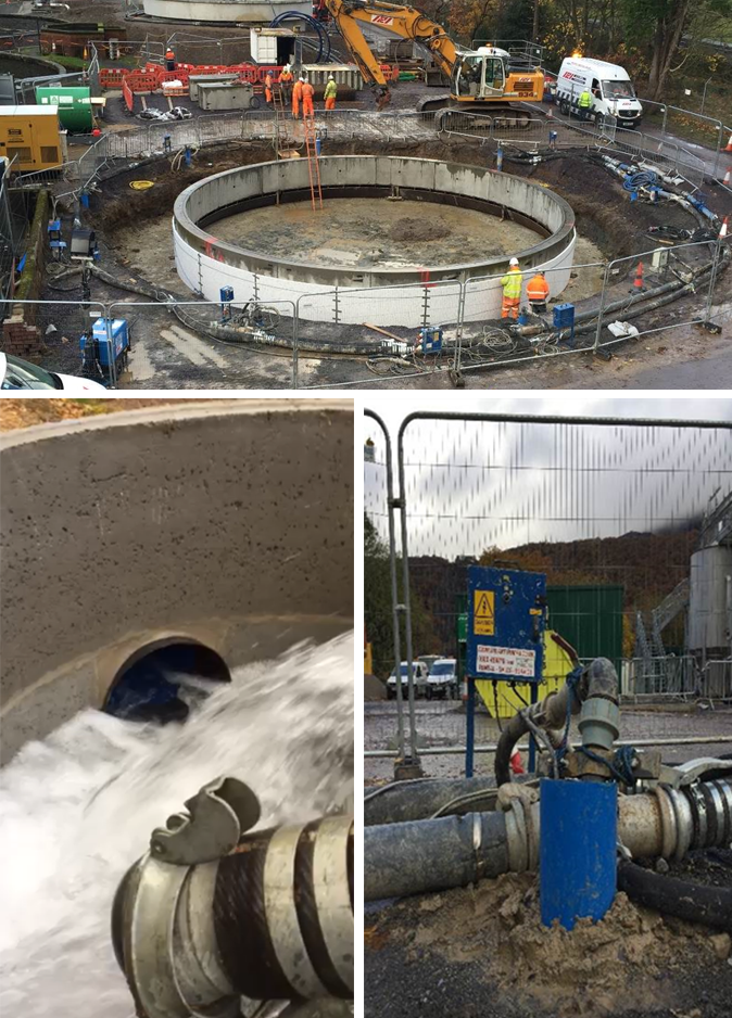
Deep Well Dewatering - Shaft Llanberis WwTW
- Client: A E Yates Trenchless Solutions Ltd
- Location: Llanberis WwTW in Gwynedd
- Duration: None
Deepwell dewatering solution for the construction of a shaft and new humus sedimentation tank
Project Overview
Stuart Wells was awarded the contract to dewater a 12.5m diameter x 5.9m deep shaft at Llanberis WwTW in Gwynedd. Ground conditions consisted of alluvium fan deposits with coarse sand and gravels overlying the Llanberis slate formation. Dewatering was operational with the initial commissioning of the pumps discharging in incremental increases of a maximum 20 lts/sec per day with a maximum increase of 5 lts/sec at any stage until the discharge water quality was confirmed. Upon acceptance of the water quality pumping was controlled and water quality monitored to mitigate environmental concerns.
Objective
The client required a dewatering solution to accommodate varying ground conditions and mitigate environmental concerns to Llyn Padarnand Afon Seiont around 220m from the shaft location. The river also acted as the discharge point for abstracted water.
Solution
9no x 15m dewatering wells were installed withborehole pumps and the shaft was successfullycompleted within 6 weeks.
Scope of Works
Borehole pumps suspended on 63mm Ø riser to a wellhead assembly. In turn the wells are connected 4no x 150mm Ø collection mains discharging via v-notch tank then to a collection MH with a 200mm Ø polybauer discharge line to river, with flotation strainer within the river yo mitigate environmental concerns with discharging into the river. Phased pumping was proposed to control the impact of flow and water quality with discharge samples taken and analysed during each phase, prior to starting the next phase.
- Phase 1 – Initial commissioning of 9no BH pumps to discharge maximum 40 lts/sec until discharge water quality confirmed.
- Phase 2 – Upon acceptance of water quality to increase the total discharge flow from the 9no dewatering wells in incremental increases of a maximum 20 lts/sec per day with a maximum increase of 5 lts/sec at any stage. Increasing to maximum flow with continuous pumping to enable construction of the shaft.

Downloadable PDF
Deep Well Dewatering - Llanberis Wastewater Treatment Works
Related Case Studies
- Deep Well Dewatering - Ashby Folville Manor
- Basement Extension
- Ejector Dewatering - Hook WwTW
- Ejector Dewatering - Islington Pumping Station
- Deep Well Dewatering - Mersey Gateway Bridge
- Deep Well Dewatering - Paull TBM Reception Shaft
- Deep Well Dewatering - Unity Square
- Deep Well Dewatering - Glass Factory
- Wellpoint Dewatering - Laing O’Rourke
- Wellpoint Dewatering - Epworth STW
- Wellpoint Dewatering - Great Wakering Housing
- Wellpoint Dewatering – Northern Gateway
- Wellpoint Dewatering – Savill Court
- Pressure Relief Wells - EDF Hinkley Point C
- Pressure Relief Wells - UCLH Proton Unit
- Pressure Relief Wells - Werrington Grade Separation

